VRSG Radar Simulation
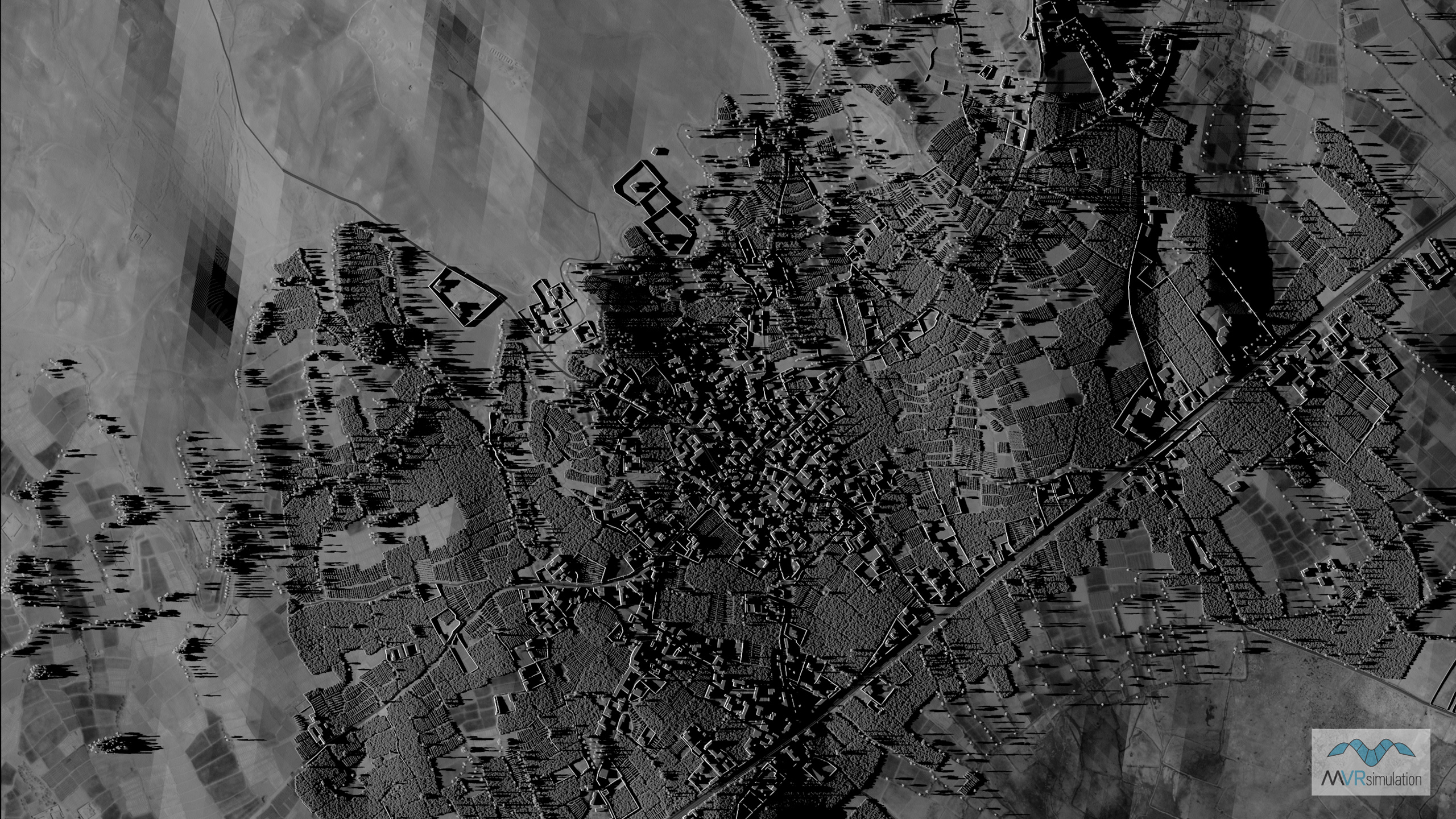
MVRsimulation VRSG Radar real-time synthetic aperture radar (SAR) display of 3D terrain of an Afghanistan village.
MVRsimulation VRSG Radar enables the simulation of a radar system to be built upon the VRSG rendering engine, using VRSG round-earth terrain tiles, culture, and moving models. VRSG Radar takes advantage of the capabilities of modern commercial graphics accelerators to solve real-time radar simulation problems that historically have required extensive custom hardware and software, at great expense.
VRSG Radar is suitable for building radar simulations such as the F-16 Digital Radar Land Mapping System (DRLMS), synthetic aperture radar (SAR) displays for Unmanned Aerial Vehicles (UAV) or other such equipped platforms.
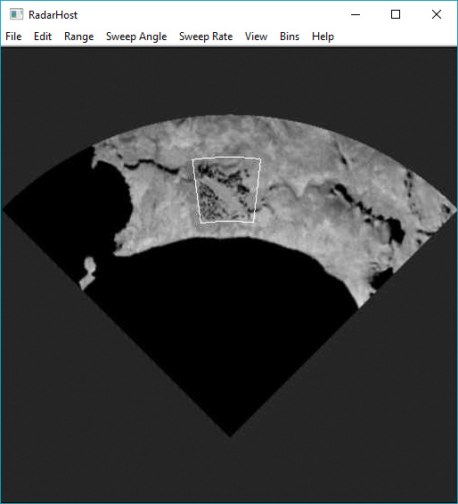
VRSG Radar assists users in constructing a radar simulation by modeling the processes of the real radar system. Developers can create a radar host system that collects the raw radar return data from VRSG Radar and presents the data in a format suitable for the system being modeled. VRSG Radar handles the complexity of modeling the beam as it travels through space, impacts objects, and simulates the amount of energy that would be returned to the radar antenna.
Requirements
The hardware requirements for running VRSG Radar are similar to those of VRSG itself; it requires a DirectX 11-capable video card.
VRSG Radar can run any set of VRSG round-earth terrain tiles that you can run with VRSG. You can run the Radar Host on the same computer as VRSG Radar, but for best performance you should run it on a separate computer. The Radar host computer does not need to be a high-end system; it requires only basic 3D capabilities.
VRSG Radar uses the same visual database as the out-the-window channels, enabling perfect correlation with visual display. You can modify certain textures to augment their reflectivity in the radar spectrum, but the databases will remain perfectly geometrically correlated.
How VRSG Radar works
VRSG Radar works in conjunction with a user-developed Radar Host. The Radar Host models the position and orientation of the radar system, and the orientation of the beam relative to the platform hosting the radar system. As the Radar Host sweeps the beam in azimuth, it sends a request to VRSG Radar for the returned raw radar data corresponding for the current radar position, orientation, beam azimuth, beam dimensions, and maximum range. VRSG Radar responds with the set of summed intensities across the quantized range space. The Radar Host in turn processes this raw radar return data for display purposes.
The Radar Host must quantize the beam sweep in azimuth into discrete “looks” it sends to VRSG Radar for processing. Thus the fidelity in azimuth is related to the beam sweep rate, and the speed in which VRSG Radar and the radar host can process each look. VRSG Radar can typically support frame rates up to 300 Hz using modern PC hardware, so a beam sweep rate of 6 degrees per second can yield an azimuth resolution of as fine as 0.02 degrees per look.
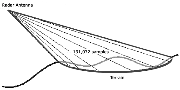
At the first point along the ray where the terrain tiles or model geometry is intersected, VRSG Radar calculates the amount of energy that would be returned; it does so by considering the incident angle of the beam with respect to the local surface normal, in conjunction with the reflectivity of the intersected material. All these things are taken into consideration in simulating the amount of energy that would be returned to the radar antenna.
The range interval requested by the radar host is quantized into a set of range bins. The Radar Host requests the number of range bins using the Radar ICD. The number of range bins can vary from 256 to 4098 depending on the application. VRSG Radar returns to the host an array of intensities, where each entry represents the summation of all intensities of all the 131,072 samples that fall into that particular range bin. It is this array of summed intensities that the radar host processes into a displayable form. Because this approach mimics how a real radar system works, subtle radar characteristics such as shadows and bright spots on front-facing objects are a natural byproduct of the implementation.
Quantizing 131,072 samples 300 times per second is over 40 million rays cast per second. Although this might seem to be an unachievable amount of processing, VRSG takes advantage of the power of DirectX 11 programmable vertex and pixel shaders to make this possible on a low-cost Windows PC platform.
Example Radar Host application
Upon request, MVRsimulation will provide an example Radar Host application, with full source code, that illustrates how to communicate with VRSG Radar and prepare returned Radar data for display. You can use this application as starting points for a new application or as an example for how to embed the funtionality into existing applications.
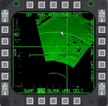
The DRLMS example illustrates the simulation of a radar system similar to that used by the F-16 digital radar land-mapping system. The images at the top of the page and below are screen captures of the DRLMS example Radar Host in action.
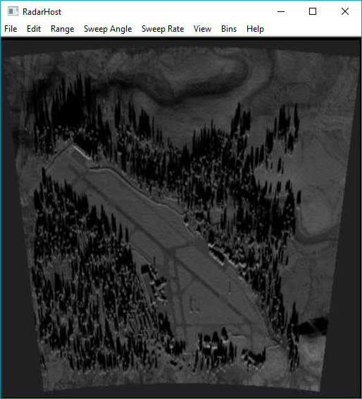
The full source code provided with the example application uses Microsoft Foundation Classes for the graphical user interface and DirectX 11 for the Radar display. Although Direct3D is used for the graphical display in the example application, the VRSG Radar architecture is graphics-API independent. You can construct a Radar host on any platform using any graphics API.
The documentation for VRSG Radar is included in the MVRsimulation VRSG User's Guide.
